Home

Majestätisch trimmen heilig negative edge triggered d flip flop truth table Gesundheit Gegenüber Reibung

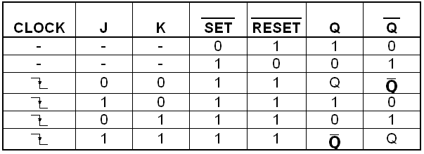
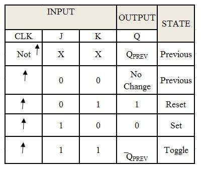
Truth Table of JK Flip Flop: Circuit Diagram and Master-Slave – Wira  Electrical
Truth Table of JK Flip Flop: Circuit Diagram and Master-Slave – Wira Electrical

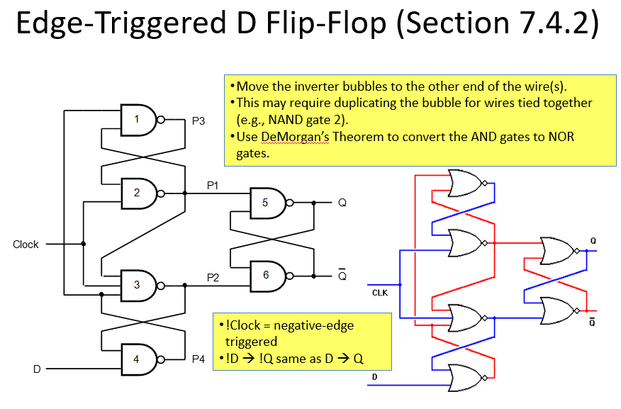
Realization of negative edge triggered D flip flop by proposed RDFF... |  Download Scientific Diagram
Realization of negative edge triggered D flip flop by proposed RDFF... | Download Scientific Diagram

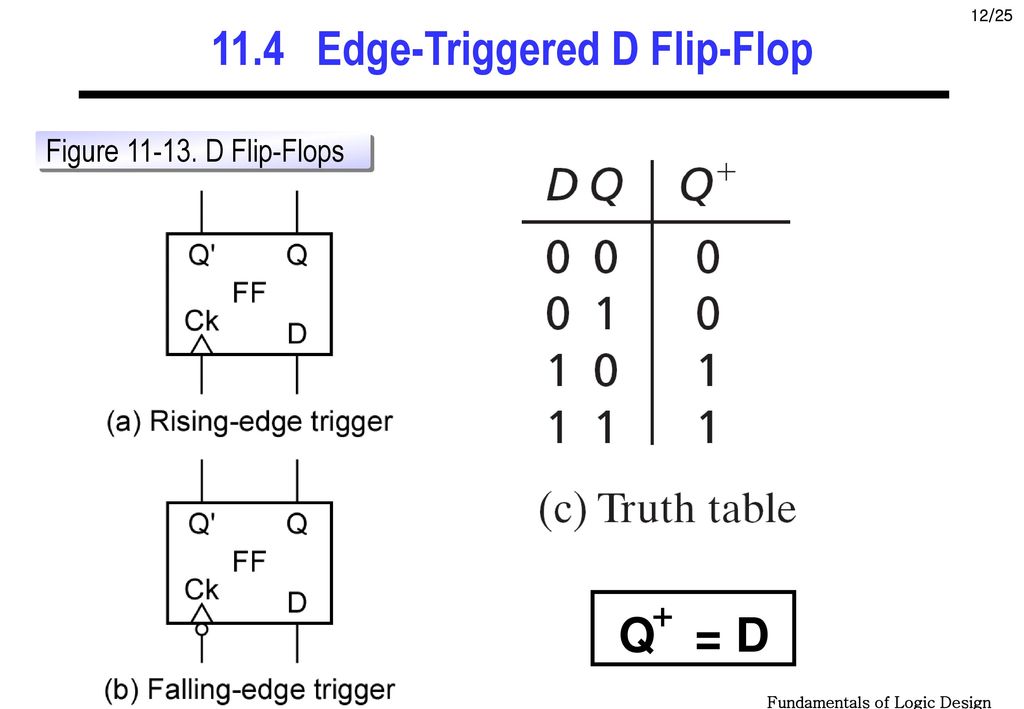
D Flip-Flop Circuit Diagram: Working & Truth Table Explained

Solved: Construct a complete truth table and timing diagram for a ... |  Chegg.com
Solved: Construct a complete truth table and timing diagram for a ... | Chegg.com

Realization of positive edge triggered D-flip flop by proposed RDFF... |  Download Scientific Diagram
Realization of positive edge triggered D-flip flop by proposed RDFF... | Download Scientific Diagram

Flip-flop circuits
Flip-flop circuits

Realization of positive edge triggered D-flip flop by proposed RDFF... |  Download Scientific Diagram
Realization of positive edge triggered D-flip flop by proposed RDFF... | Download Scientific Diagram

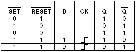
Flip-flop Types, Logic symbols, Truth Table & Applications - study notes

The Integrated-Circuit D Latch (7475)

D Flip Flop With Preset and Clear : 4 Steps - Instructables

Sequential Logic Types of digital systems 1 Combinational

Is S R flip flop positive level triggered or negative level triggered? -  Quora
Is S R flip flop positive level triggered or negative level triggered? - Quora

D Type Flip Flop: Circuit Diagram, Conversion, Truth Table

Verilog for Beginners: D Flip-Flop

FlipFlops Logic Circuits Gates are referred to as

Flip-flop circuits
Flip-flop circuits

LATCHES AND FLIP-FLOPS - ppt download

D Type Flip Flop: Circuit Diagram, Conversion, Truth Table

Objectives: Given input logice levels, state the output of an RS NAND and  RS NOR. Given a clock signal, determine the PGT and NGT. Define “Edge  Triggered” - ppt download
Objectives: Given input logice levels, state the output of an RS NAND and RS NOR. Given a clock signal, determine the PGT and NGT. Define “Edge Triggered” - ppt download

Solved Referring to the negative-edge triggered D flip-flop | Chegg.com

Designing JK FlipFlop

Solved: Chapter 7 Problem 15P Solution | Digital Fundamentals 11th Edition  | Chegg.com
Solved: Chapter 7 Problem 15P Solution | Digital Fundamentals 11th Edition | Chegg.com